Paramount 300B to Paramount 2A3 Conversion
In five simple steps
Step one – filament choke FC-1 reconfiguration
Remove the wires that connect terminals 2 and 4, and 7 and 9.
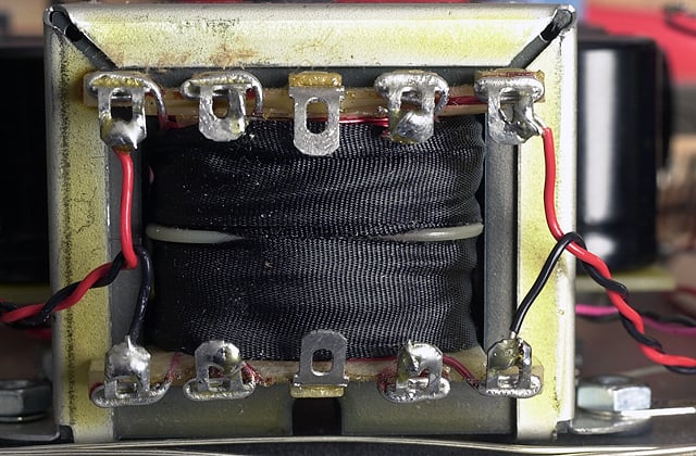
Replace the removed jumpers with 2″ long wires that connect terminal 1 to 4, 2 to 5, 6 to 9, and 7 to 10.
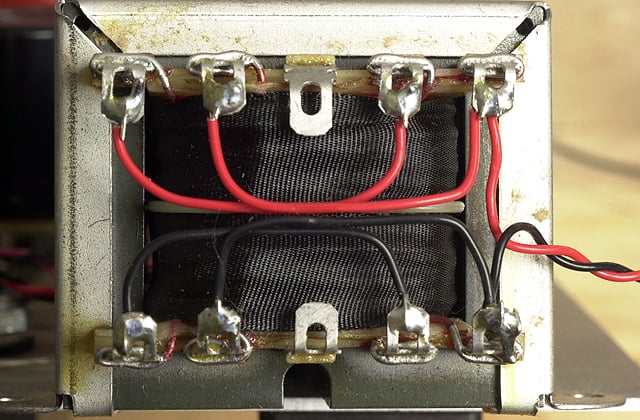
Step two – filament supply reconfiguration
Unbolt and move back the FC-1 filament choke to make clearance at the back of the power supply PC board.
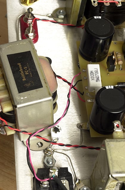
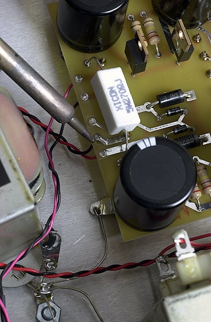
Desolder and move the the black filament supply wire (connected to FC-1 terminal 5 at the other end) one solder pad closer to the plate choke end of the power supply PC board and solder it. Re-install the FC-1 filter choke.
Step three – output stage grid reconfiguration
Remove the 0.1uF capactor from terminals 7 and 9, and also remove the 249K ohm resistor from terminals 7 and 10.
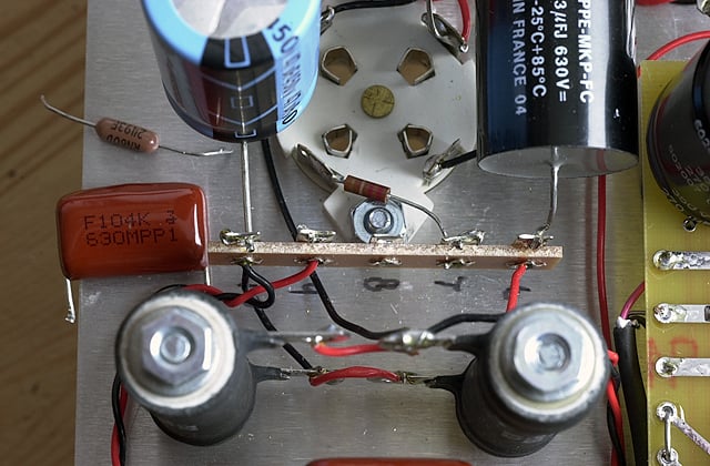
Install and solder a 1″ jumper wire from terminal 7 to terminal 9.
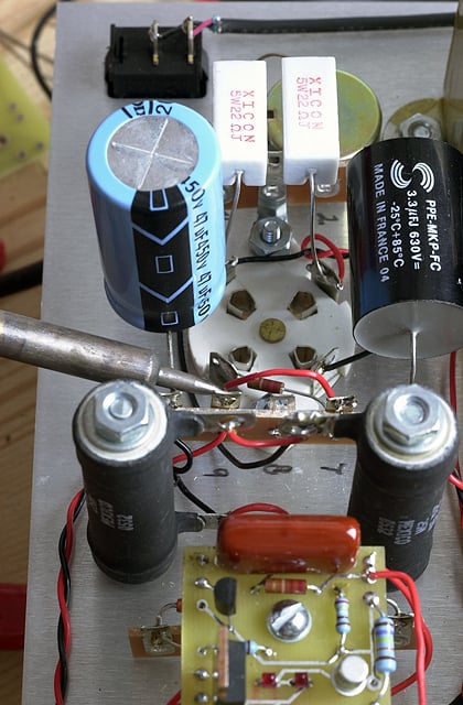
Step four – cathode resistor reconfiguration
Remove the wire that connects the upper terminal of the cathode resistors to each other and also the wire that connects the lower terminal of the cathode resistors to each other.
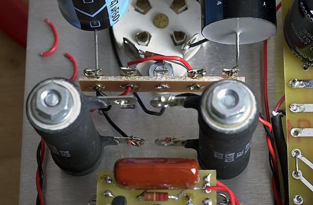
Install and solder a 2″ wire that connects the upper terminal of the front cathode resistor to the lower terminal of the rear cathode resistor.
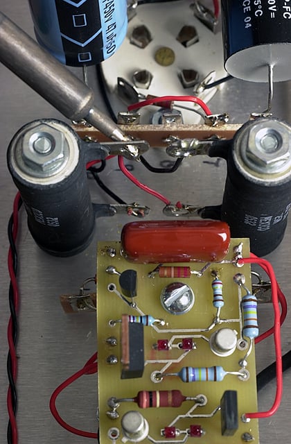
Step five – driver bias reconfiguration
Remove the screws from the C4S/shunt regulator PC board and lift the board up and back to allow access to the nine pin socket. Remove the TL431 adjustable shunt regulator from pin B3 and center terminal of the nine pin socket.
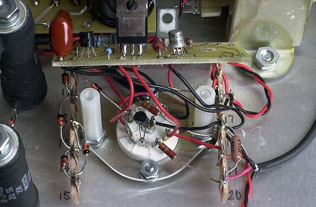
Install and solder an HLMP-6000 LED to pin B3 and the center terminal of the nine pin socket, with the silver end facing the center terminal. Re install the PC board on the standdoffs.
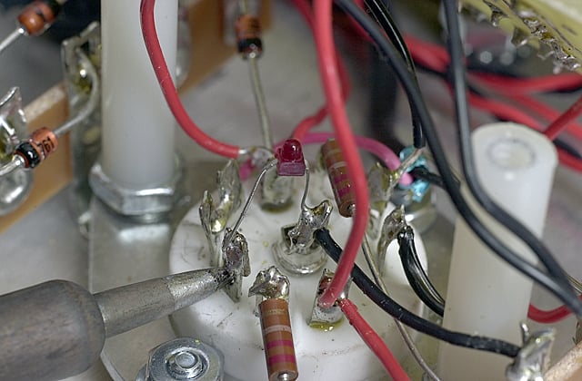
Check resistance readings against the manual. Then install a 2A3 tube, plug the amp in, and check voltages against the manual. Adjust the hum balance of the 2A3 and you are ready to listen to some music.
